Before You Start
Watch the Demonstration Video
The above video is of our WiFi only Interface Kit installation, so the hardware in the video is slightly different than yours. Despite that, it should be very helpful and 95% applicable to your Pro Interface Kit installation.
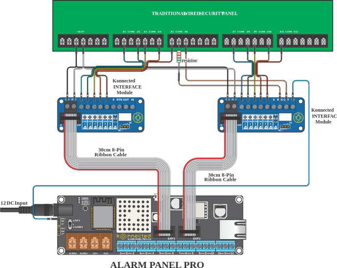
Inspect the Wiring Illustration
Getting Started
- Disconnect the power and backup battery from the traditional wired alarm system before you begin.
- Mount the Interface module near the wired zones of the traditional alarm panel, and connect using the included ribbon cable to the Konnected Alarm Panel / Add-on Panel / Pro. Each 6-zone Interface module requires a connection to a Konnected Alarm Panel board.
- Identify the AUX output (usually 12VDC) on the traditional alarm panel. Connect GND and VREF on the Interface module to AUX- and AUX+ on the traditional panel, respectively. This is necessary to provide an operating voltage reference to the Konnected device.
- Connect the zone inputs 1 - 6 on the Interface module to the wired zones (high side or zone side) on the traditional panel. Be careful to leave the existing wires intact!
- Power back on the traditional panel, reconnect the backup battery, and plug in the Konnected Alarm Panel. The green power light should illuminate on the Konnected Alarm Panel, and six orange zone lights should illuminate on the Interface module.
- If you have more additional zones to be monitored you will repeat this wiring minus the keyswitch/relay with the additional boards.
Tuning the Zone Inputs on the Interface Module
The inputs on the Interface module need to be tuned after installation to account for different resistance values on your wired sensors. This only needs to be done once.
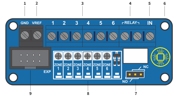
- When each zone is closed (i.e. the door/window is closed or motion is not detected), the orange LED corresponding to that zone should be illuminated.
- If the orange LED is not illuminated and the zone is closed, using a small screwdriver tip with very gentle pressure, turn the small dial above the zone number clockwise until the orange LED turns on.
- If the orange LED is illuminated, turn the dial counter-clockwise until the orange LED turns off, then gently turn it back clockwise until the orange LED just turns on again.
- The objective of tuning is to adjust the potentiometer dial until the orange LED is just past the threshold of on/off and remains on when the zone is closed.
- Ask a helper to open the zone (open the door/window or trip the motion) and observe the orange LED for that zone turning off when the zone is open, and turning back on when the zone is closed. When this happens without any flickering, the zone is properly tuned.
If your sensors do not have any resistors, the orange LED may never turn off when the zone is closed. In that case, turn the dial all the way counter-clockwise until it stops (don't force it!) and check that the orange LED turns off when the zone is opened.
Tuning with Programmable Outputs
Programmable outputs on most traditional alarm panels work the same way as wired zones. Program the output to signal various conditions with a low/high binary signal. For example "Armed" = high; "Disarmed" = low.
Connect the programmable output to a zone input on the Konnected Interface module, and tune it in the same way described above. The orange LED should remain on when the output is low, and should turn off when the output is high.