Product Information 1
Key Features and Benefits
- Higher Quality Hardware: Based on the ESP32 microcontroller, a newer and more powerful option (as compared to our 6 zone WiFi boards) that will allow future Matter standard compatibility and Matter integration.
- Retained System Functionality: Allows your current alarm system to function with smart home capabilities, maintaining its original features.
- Advanced Smart Home Integration: Compatible with leading smart platforms for extensive control and automation possibilities.
- Remote Management: Enables monitoring and control of your security system from anywhere, ensuring peace of mind.
- Open-Source Flexibility: Utilizes open-source software for ongoing enhancements and customization.
- Robust Connectivity Options: Offers Ethernet and PoE for a more reliable and versatile setup.
Important Information:
- Side-by-Side System Integration: This kit operates alongside your existing alarm system, keeping keypads and sirens active.
- Check Your Alarm System's Capabilities: Verify that your existing system supports at least 2 programmable outputs and a key switch, and that you have the ability to modify the programming (you have the "master installer code/programming code/installer programming code").
- Network Enhancements: Supports Ethernet with fail-over WiFi, providing a more dependable connection.
- PoE Support: Utilizes PoE for efficient installation, powering the device through a network cable.
- Installation Code Knowledge: May need the existing system’s installation code for integrating specific functionalities.
- Community and Support: Access to Konnected’s community for setup help and system customization.
What’s in the Box?
Your Konnected Alarm Panel Pro Interface Kit includes the following items:
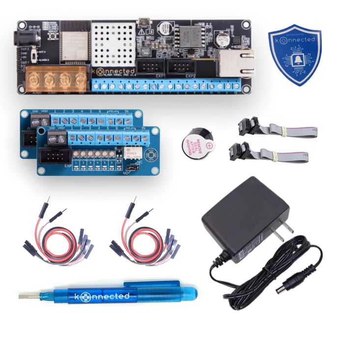
- 12-Zone Alarm Panel Pro Board
- 2x Interface Module w/ Built-In Relay
- Piezo Buzzer: Comes with jumper wires
- 12V Power Adapter: Provides power to the alarm panel if not using PoE
- Installation Accessories:
- Jumper Wires
- Konnected window sticker
- Sheet of wire labels for easy identification
- Adhesive-backed standoffs for mounting
- Mini screwdriver pen for assembly
- Welcome card containing instructions and information
Table of Contents 2
Setup Overview
The following steps provide an overview of the steps involved in wiring your Konnected Alarm Panel Pro Interface Kit in-parallel with your Traditional Alarm Panel
- Connecting to Your Network
-
Connecting to Your Network (for SmartThings users only)
Method #1: Konnected Mobile App (Recommended)
Before connecting via Ethernet, we recommend that you follow our Wi-Fi setup process to store your Wi-Fi credentials. This way, in the event of Ethernet connection issues, your Konnected Alarm Panel Pro will automatically fail-over to Wi-Fi.
- Download: Get the Konnected app for iOS or Android.
- scan the code below for iOS
- scan the code below for android
.png?width=150&height=150&name=adobe-express-qr-code%20(1).png)
- Power one Konnected board (steps will be repeated for additional boards) with the included power supply.
- Launch: Start the app and select 'Add New Device'.
- Wi-Fi Setup: Follow on-screen instructions to enter WiFi details and finalize the setup.
- Confirmation: Look for a non-blinking blue light on the board as a success indicator.
- Multiple Boards: Repeat for each board you have.
-
Connecting via Ethernet
Once you've succesfully connected all of your Konnected Alarm Panel Pro boards via Wi-Fi, you can go ahead and connect Ethernet to them. If you are using PoE, you can remove the power supply... if you do not have PoE, keep using the power supply.
- Power and connect to Ethernet to one Konnected board (steps will be repeated for additional boards).
- Launch: Start the app and select 'Add New Device'.
- Connection: Click "Skip" down in the bottom right corner to skip the Wi-Fi setup step since your board is connected via Ethernet.
-
- Identifying Your Wiring
-
Identifying Your Wiring
Proper identification and labeling of your existing wiring are paramount for successfully installing the Konnected Alarm Panel Conversion Kit. Follow these steps to ensure accuracy:
Documentation
- Photograph Your Setup: Capture high-quality images of your current alarm panel, wiring, and any zone lists or diagrams you have.
Labeling
- Use Provided Labels: Apply the included label stickers to each wire, noting their corresponding connections for easy reference.
Wire Identification
- Recognize Wire Types: For a comprehensive guide on wire labels such as AC +/-, Aux +/-, Bell +/-, Data, Zones, and Telephone, please refer to our detailed 📄 Identifying Your Wiring documentation.
- 2-Strand Wires: Typically used for sensors.
- 4-Strand Wires: Commonly connect motion detectors and keypads.
- Red/Black Wires: Usually indicate power connections.
AC Power Caution: Never attach AC power wires directly to the Konnected board.
-
- Mounting and Positioning
-
Mounting and Positioning
Location
- Near Existing Wiring: Install the Konnected Panel, which can easily connect to your wired sensor wires or the original wiring panel.
Enclosure Options
- 3D Printed Enclosure: Consider a tailored enclosure for a secure and neat fit.
- Reuse Metal Enclosure: Alternatively, you may repurpose the enclosure of your old system. We've found that WiFi signal interference from metal enclosures is often insignificant.
Installation
-
- Mounting Options: Secure the device using magnetic or adhesive standoffs.
- WiFi Proximity: Position the panel within a good range of your router to ensure a robust WiFi signal.
- Interference Precautions: Avoid placing the device near high-voltage wiring to minimize potential interference.
-
- Wiring and Programming Guide
-
Getting Started
- Disconnect the power and backup battery from the traditional wired alarm system before you begin.
- Mount the Interface module near the wired zones of the traditional alarm panel, and connect using the included ribbon cable to the Konnected Alarm Panel / Add-on Panel / Pro. Each 6-zone Interface module requires a connection to a Konnected Alarm Panel board.
- Identify the AUX output (usually 12VDC) on the traditional alarm panel. Connect GND and VREF on the Interface module to AUX- and AUX+ on the traditional panel, respectively. This is necessary to provide an operating voltage reference to the Konnected device.
- Connect the zone inputs 1 - 6 on the Interface module to the wired zones (high side or zone side) on the traditional panel. Be careful to leave the existing wires intact!
- Power back on the traditional panel, reconnect the backup battery, and plug in the Konnected Alarm Panel. The green power light should illuminate on the Konnected Alarm Panel, and six orange zone lights should illuminate on the Interface module.
- If you have more additional zones to be monitored you will repeat this wiring minus the keyswitch/relay with the additional boards.
Tuning the Zone Inputs on the Interface Module
The inputs on the Interface module need to be tuned after installation to account for different resistance values on your wired sensors. This only needs to be done once.
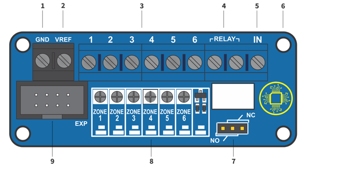
- When each zone is closed (i.e. the door/window is closed or motion is not detected), the orange LED corresponding to that zone should be illuminated.
- If the orange LED is not illuminated and the zone is closed, using a small screwdriver tip with very gentle pressure, turn the small dial above the zone number clockwise until the orange LED turns on.
- If the orange LED is illuminated, turn the dial counter-clockwise until the orange LED turns off, then gently turn it back clockwise until the orange LED just turns on again.
- The objective of tuning is to adjust the potentiometer dial until the orange LED is just past the threshold of on/off and remains on when the zone is closed.
- Ask a helper to open the zone (open the door/window or trip the motion) and observe the orange LED for that zone turning off when the zone is open, and turning back on when the zone is closed. When this happens without any flickering, the zone is properly tuned.
If your sensors do not have any resistors, the orange LED may never turn off when the zone is closed. In that case, turn the dial all the way counter-clockwise until it stops (don't force it!) and check that the orange LED turns off when the zone is opened.
Tuning with Programmable Outputs
Programmable outputs on most traditional alarm panels work the same way as wired zones. Program the output to signal various conditions with a low/high binary signal. For example "Armed" = high; "Disarmed" = low.
Connect the programmable output to a zone input on the Konnected Interface module, and tune it in the same way described above. The orange LED should remain on when the output is low, and should turn off when the output is high.
-
- Wiring a Key Switch
-
Remotely arm and disarm a traditional wired alarm system using Konnected and a relay module to trigger a keyswitch zone.
To remotely arm/disarm using this method, you must have an unused zone on the traditional alarm panel that can be assigned as a keyswitch. This means you'll need the panel's installer code and a keypad capable of programming it.
A keyswitch zone type is supported by most traditional systems to arm/disarm the device with a momentary contact closure or opening. Think of a physical "key switch" that arms the alarm when you insert and turn a key. In this setup, we use a relay module, controlled by commands from your smart home platform to Konnected, to make that momentary connection.
- Identify an unused zone on the traditional alarm panel. Follow the alarm panel's programming guide to program this zone as a keyswitch zone.
- Connect the keyswitch zone and its adjacent COM terminal to the terminals marked RELAY on the Konnected Alarm Panel INTERFACE module.
- If the traditional panel requires a specific resistance value, wire the appropriate resistor inline with either the keyswitch zone. Not all panels require a resistor, and some can be programmed to work with or without one.
- Connect IN terminal on the INTERFACE module to the OUT terminal or pin on the Konnected Alarm Panel, or either OUT1 or OUT2 pin on the Alarm Panel Pro.
Configure the OUT zone
In your smart home platform, configure the OUT zone as a Switch or Momentary switch to activate the relay.
SmartThings: Use the Konnected app to set up
Built-in Dry Contact Relay
The Alarm Panel INTERFACE module v2.1 features a built-in dry contact relay that can be used to actuate a keyswitch or many other things:
- Garage door opener
- Electronic door strike
- LED light
- Sounder or strobe
- Any circuit up to 2A 30VDC or 0.3A 125VAC
The built-in relay is activated by applying 3.3V to the IN terminal, and is designed to be triggered from the Konnected Alarm Panel Add-on or Konnected Alarm Panel Pro OUT terminals.
Normally Open vs. Normally Closed
Depending on the capabilities of your traditional alarm panel, the keyswitch may need to be configured Normally Open (NO) or Normally Closed (NC). Normally open means that the circuit is open until the trigger voltage is applied to the IN terminal, which causes the relay to close.
Move the jumper cap on the Alarm Panel INTERFACE module to the NO or NC position to set the desired behavior.
-
- Powering Your Konnected Board
-
Powering Your Konnected Board
Choose from multiple power supply options to ensure your Konnected Alarm Panel operates efficiently.
Powering Options
- Existing Alarm System: Utilize the 12V DC power from your previous alarm system's power supply.
- Board Specifications: The board is compatible with a range of 6V to 24V DC or 5V via USB.
- Included Power Adapter: Plug the included power adapter into a standard outlet for a simple setup.
- USB Powering: While USB is an option for board power, it won't support high-draw devices like sensors or sirens.
- Multiple Boards: Utilize a splitter cable if you're setting up multiple boards.
- Reusing Wiring: If repurposing existing wiring, first ensure to disconnect the old system's power and battery.
-
- Choosing Your Smart Home Platform
- PLEASE SEE DETAILED GUIDE VIA THE LINK ABOVE FOR SMOKE AND CARBON MONOXIDE DETECTOR WIRING INFORMATION